This article explains the concept of shear lag and plate buckling in plated structures as espouses in EN 1993-1-5, and also how to incorporate their effects during analysis and design (resistance check)
Peculiar Problem of Plated Structures
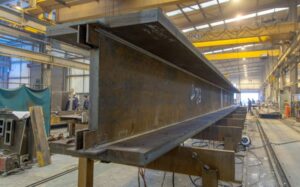
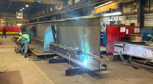
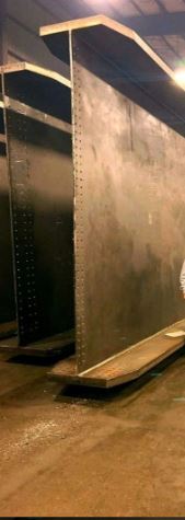
Plate girders are fabricated sections that are built by welding together different plates to make up for the absence of rolled sections that can perform adequately for the intended use. During fabrication, there is need to balance between economy of material and the performance of the section. The section is needed to be deep enough to have large moment of inertial about the major axis and in turn high bending stiffness. The attendant consequence is that the web will be too tall and will often end up being slender. Conversely, designing a web that is not slender implies excessive thickness, which signifies inefficient material usage. This would significantly increase the cost of fabrication of the section and also add to the cost of foundation to bear redundant weight.
Furthermore, for efficiency, the flanges are needed to be wide to provide a chunk of cross-sectional area at the extreme fiber, far from the neutral axis. This also has an attendant consequence called shear lag. Shear lag is the phenomenon where the longitudinal stresses in the flange are not uniform, but instead gradually decreases as the distance from the web increases. This implies the part of the flange furthest from the web lags behind in resisting stress.
Often times for plated girders, maintaining a modest web height and flange width such that the section remains within class 1 to class 3 might suggest a standard rolled section would have sufficed, potentially rendering the complexity of a fabricated plate girder unnecessary. Therefore, the design of efficient plated structures is fundamentally a management of buckling and non-linear stress distributions, such as shear lag.
EN 1993-1-5 Provisions
EN 1993-1-5 is the primary standard in structural Eurocodes on design of stiffened and unstiffened plates subject to in-plane forces. As such it is largely focused on how to achieve an optimal section of girders taking account of the effects of two phenomenon of shear lag and plate buckling.
According to the standard, these two effects shall be accounted for during global analysis and member resistance check. EN 1993-1-5 provides three approaches for incorporating these effects into plate design:
- Effective width method – simplifies stress distribution by reducing the effective width of the plate.
- Reduce stress method – accounts for non-uniform stress by applying reduction factors.
- Finite Element Method – provides a more rigorous numerical analysis of stress and buckling behavior.
This article majorly discusses the effective method
Key Terminologies
Before diving further, we have to introduce key terminologies that shall be used throughout the article as we proceed.
effectives : When this precedes a property, it denotes the property is derived having considered the effect of shear lag.
So that:
effectives width becomes the effective width of the member due to shear lag
effectives area becomes the ffective area of the member due to shear lag, etc.
effectivep : When this precedes a property, it denotes the property is derived having considered the effect of plate buckling.
So that:
effectivep width becomes the effective width of the member due to plate buckling
effectivep area becomes the effective area of the member due to plate buckling, etc.
effective : When this precedes a property, it denotes that the property is derived having considered the combined effect of shear lag and plate buckling
Effective Width Model for Global Analysis of Plate Girders
Shear lag and plate buckling reduce the stiffness of plated structures, which should be accounted for in global analysis to accurately capture the distribution of stresses in the cross-section. Section 2 of EN 1993-1-5 stipulates recommendations to account for the correct stiffness of plate girders in global analysis for modeling these effects to ensure the calculated stiffness represents the real-world behavior of the member. This is done by modelling the effects of shear lag and plate buckling. The techniques for modelling these effects are discussed below:
Effective Width Due to Shear Lag for Global Analysis
The effects of shear lag of flanges in global analysis may be taken into account by the use of an effectives width. This effective width can be assumed to be uniform throughout the span of the member. For each span of a member the effectives width of flanges should be taken as the lesser of the full width and L/8 per side of the web, where L is the span or twice the distance from the support to the end of a cantilever.
Effective Width Due to Plate Buckling for Global Analysis
The effects of plate buckling in elastic global analysis may be taken into account by effectivep cross sectional areas of the elements in compression. However, if the effective area is large enough (i.e.: larger than ρlim times the gross area), the effect of plate buckling can be ignored and the gross properties can be used. The value recommended for ρlim in the standard is 0.5.
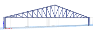
Analyzing Complex Shape and Irregular members
Finite element Method should be used to model and analyze complex members such as hunched members, members with large openings, members with irregular panels, so that the effect of shear lag and plate buckling are capture in the global analysis.
Effective Width Model for Resistance Check
Once the global analysis is complete and the internal forces (MEd, NEd and VEd, ) are determined, the member must be verified for resistance. As plated structures often falls under the category of Class 4 cross-sections where local plate buckling occurs before the yield strength is reached, To prevent this, EN 1993-1-5 uses effective width method for the ultimate limit state (ULS) verification.
The effective width allows the resistance of the section to be determined based on post-buckling reserve of each buckled plates. This method assumes that the central, buckled portion of a slender plate is ineffective at carrying further load, redistributing the stress toward the supported edges (the stiffened boundaries).
Effective Width due to Shear Lag for Resistance Check
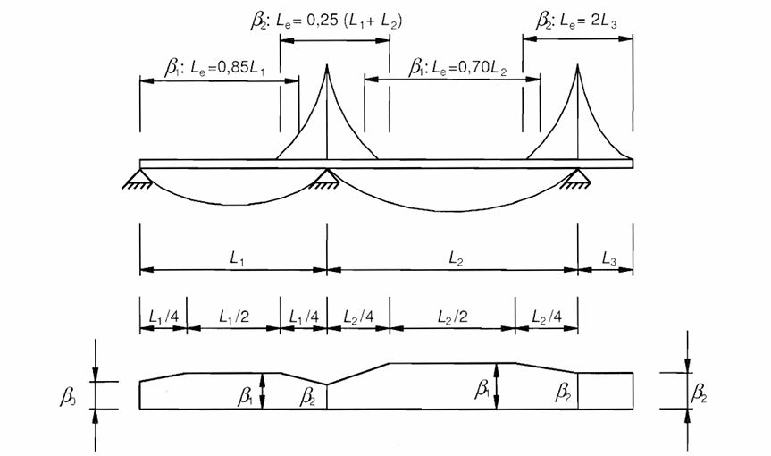
According to clause 3.1 (1) of EN 1993-1-5, Shear lag in flanges may be neglected if bo < Le/50 (Where; bo is taken as the flange outstand or half the width of an internal element and Le, is the length between points of zero bending moment.)
However, if the condition aforementioned is not satisfied, the effective width due to shear lag for resistance check should be estimated as follows.
Effective Width due to Shear Lag under elastic Condition
The effective width for shear lag under elastic conditions (serviceability and fatigue limit states) should be determined from:
beff = β bo
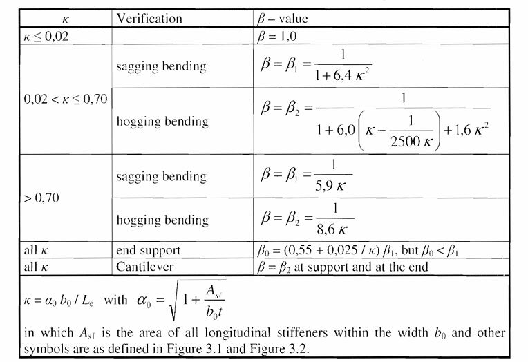
where β is the effective width factor which can be determined by using table 3.1 of EN 1993-1-5 which is reproduced below
The effective area determined from effective width due to shear lag becomes:
Aeff = beff x t
Effective Width of Shear Lag at Ultimate Limit State
At the ultimate limit state shear lag effects may be determined as follows:
a) elastic shear lag effects as determined for serviceability and fatigue limit states
b) combined effects of shear lag and of plate buckling
c) elastic-plastic shear lag effects allowing for limited plastic strainsa)
a)The elastic shear lag has been treated in the immediate section under “Effective width due to shear lag under elastic condition” The other two options are discussed below:
b) The combined effects of plate buckling and shear lag may be taken into account by using as given by:
Aeff = Ac, eff βult
Where;
Ac, eff is the effectivep area of the compression flange due to plate buckling
βult is the effectives width factor for the effect of shear lag at the ultimate limit state, which may be taken as β determined from table 3.1, EN 1993-1-5 with ∝o replaced with:
$$
\alpha _o*\,\,=\,\,\sqrt{\frac{A_{c,eff}}{b_o\,\,t_f}}
$$
tf is flange thickness
Note: Buckling only occurs in plate under compression hence effective area due to buckling is denoted by Ac,eff. If shear lag is also pronounced in the plate, then the effective area due to plate buckling is multiplied by effective width factor due to shear lag βult or β as the case may be. This is done for every plate in the girder and the summation of the total effective area gives the effective area of the section.
As stated earlier and for emphasis, if the plate is under tension, then buckling would not occur so only shear lag is accounted for if necessary to calculate the effective area. If shear lag is also negligible then the gross area of the plate is adopted.
c) Elastic-plastic shear lag effects allowing for limited plastic strains may be taken into account using
Aeff = Ac, eff βk ≥ Ac, eff β
Effective With due to Plate Buckling for Resistance Check due to direct stresses
The resistance of plated members should be determined using the effectivep areas of plate elements in compression for class 4 sections using cross sectional data (Aeff, Ieff , and Weff ) for cross sectional verifications. The member verifications for column buckling and lateral torsional buckling according to EN 1993-1-1 using the effective properties.
For the model in the standard to be applicable, the following criteria shall be met:
a) The panels are rectangular and flanges are parallel or nearly parallel
b) Stiffeners, if any, are provided in the longitudinal or transverse direction or both;
c) Open holes and cut outs are small and does not exceed 0.05b, where b is the width of the panel.
d) Members are of uniform cross section
e) No flange induced web buckling occurs.
Plate Element without longitudinal Stiffeners
For plate element without longitudinal stiffeners, the effective area is determined as follows:
Ac, eff = ρ x Ac
ρ is the reduction factor for plate buckling
The reduction factor ρ may be taken as follows:
Internal compression elements
$$
\rho \,\,=\,\,\text{1.0\,\,}for\,\,\lambda _p\,\,\leqslant \,\,\text{0.5\,\,}+\,\,\sqrt{\text{0.085\,\,}-\,\,0.055\varPsi}
$$
$$
\rho \,\,=\,\,\frac{\lambda _{p\,\,}-\,\,0.055\left( \text{3\,\,}+\,\,\psi \right)}{\lambda _p^2}\,\,\leqslant \,\,\text{1\,\,}for\,\,\lambda _p\,\,>\,\,\text{0.5\,\,}+\,\,\sqrt{\text{0.085\,\,}-\,\,0.055\varPsi}
$$
Outstand compression elements
ρ = 1.0 for λp ≤ 0.748
$$
\rho \,\,=\frac{\lambda _p\,\,-\,\,0.188}{\lambda _p^2\,\,}\,\,\leqslant \,\,\text{1\,\,}for\,\,\lambda _p\,\,>\,\,0.748
$$
where
λp is the plate slenderness which is given as : $$
\sqrt{\frac{f_y}{\sigma _{cr}}}\,\,=\,\,\frac{\frac{b}{t}}{28.4\varepsilon \sqrt{k_{\sigma}}}
$$
Ψ is the stress ratio
b is the appropriate width to be taken which as listed below:
bw is for webs
b is for internal flange element (except for RHS)
b – 3t for flanges of RHS
c for outstand flanges
h for equal leg and unequal leg angles
σcr is the elastic critical plate buckling stress
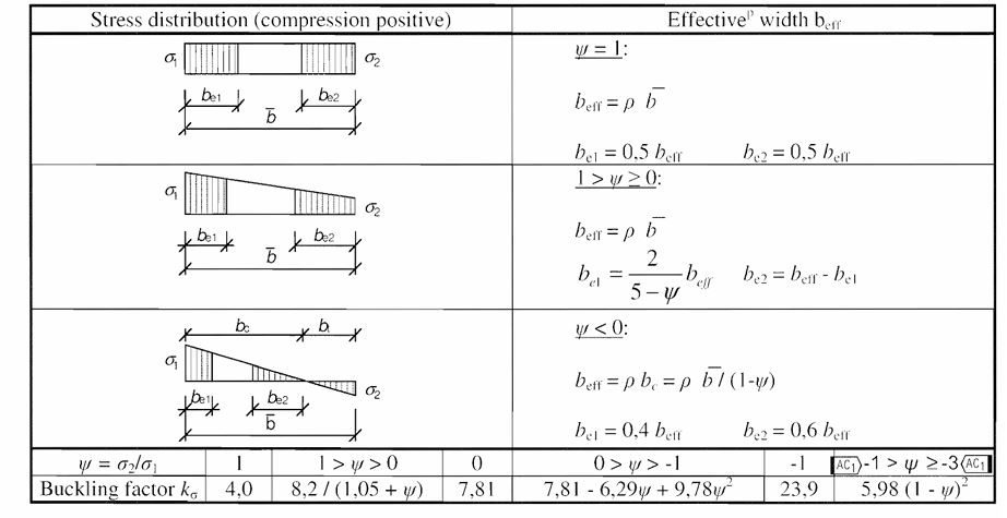
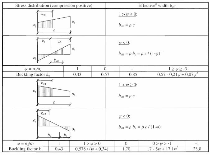
Kσ is the buckling factor corresponding to the stress ratio Ψ and boundary conditions. For long plates Kσ is given in either table 4.1 or table 4.2 of the standard. The tables are reproduced below:
Stiffened Plate Element with Longitudinal Stiffener
For plates with longitudinal stiffeners, the effectivep areas from local buckling of the various subpanels between the stiffeners and the effectivep areas from the global buckling of the stiffened panel would be accounted for. The global buckling of the stiffened panel is always somewhere between plate type buckling and column type buckling so an interaction factor is necessary to account for both tendencies.
The effectivep area of stiffened plate in compression zone is given by:
Ac, eff = ρc x Ac,eff,loc+ ∑bedge,eff t
Where;
ρc is the reduction factor for gobal buckling taking account for both column buckling and plate buckling. This shall be discussed in subsequent section below
Ac,eff,loc is effectivep area of all the stiffeners and subpanels that are fully or partially in the compression zone except the effective parts supported by an adjacent plate element with the width bedge,eff
Effective Area Due to Local Buckling (Ac,eff,loc)
Before calculating the critical stresses due to global buckling, the local buckling of subpanels and stiffeners have to be determined so that the appropriate effective properties can be used when determining the global properties. Ac,eff,loc tells how much of the stiffeners and subpanels in the cross-section within the compression zone can be considered effective in resisting load, after accounting for local buckling and shear lag. This ensures that the stiffness of the panels is not overestimated while determining the global buckling resistance.
As already declared, Ac,eff,loc is effectivep area of all the stiffeners and subpanels that are fully or partially in the compression zone except the effective parts supported by an adjacent plate element with the width bedge,eff
Ac,eff,loc is guven by:
Ac,eff,loc = Ast,eff + ∑ ρloc bc,loc t
∑ ρloc bc,loc t is the sum of the area of the stiffened panel width that is in compression except the parts bedge,eff
Ast,eff is the sum of the effectivep sections of all longitudinal stiffeners with gross area Ast located in the compression zone;
bc,loc is the width of the compressed part of the subpanel
ρloc is the reduction factor for the sub panel
Effective Area Due to Global Buckling
The global buckling of plate with longitudinal stiffeners is a fusion between a plate-type and column-type. The interpolation factor Ƹ is used to merge these two behaviors and subsequently used to determine the global reduction factor ρc
Plate type Behaviour
This assumes the stiffened panel is supported on all four sides and behaves as single unit. It resists buckling by bending and twisting in two directions. The slenderness is given as:
$$
\lambda _{p\,\,}=\,\,\sqrt{\frac{\beta _{AC\,\,}.\,\,f_y}{\sigma _{cr,p}}}
$$
σcr,p is the elastic critical plate buckling stress for the stiffened panel. This is usually calculated using the formulas in Annex A.1.
$$
\beta _{A,C}\,\,=\,\,\frac{A_{c,eff,loc}}{A_c}
$$
The reduction factor ρ for plate buckling is determined just like that of unstiffened plate element discussed earlier above provided that plate slenderness λp is determined using expression in this section
Column type Behaviour
This assumes the longitudinal stiffeners and the attached plate which is the contributing plate width act like a series of independent columns between the transverse stiffeners. The slenderness due to column buckling is given as:
For unstiffened plate
$$
\lambda _C\,\,=\,\,\sqrt{\frac{f_y}{\sigma _{cr,c}}}
$$
$$
\sigma _{cr,c}\,\,=\,\,\frac{\varPi ^2\,\,E\,\,t^2}{12\left( \text{1\,\,}-\,\,v^2 \right) \,\,\alpha ^2}
$$
For stiffened plate
$$
\lambda _{c\,\,}=\,\,\sqrt{\frac{\beta _{AC\,\,}.\,\,f_y}{\sigma _{cr,c}}}
$$
$$
\sigma _{cr,st\,\,}=\,\,\frac{\pi ^2\,\,E\,\,I_{st,I\,\,}}{A_{st,I}\,\,a^2}
$$
$$
with\,\,\beta Ac\,\,=\,\,\frac{A_{st,I,eff}}{A_{st,I}}
$$
Ist,I is the second moment of area of the stiffener and the adjacent parts of the plate
Ast,I is the gross cross-sectional area of the stiffener and the adjacent parts of the plate.
Ast,I,eff is the effective cross-sectional area of the stiffener and the adjacent parts of the plate with due allowance for plate buckling
a is the distance between transverse stiffeners.
Having gotten the column slenderness λc , the reduction factor χc is determined using EN 1993-1-1. For unstiffened plates a = 0.21 corresponding to buckling curve a should be used. For stiffened plates its value should be increased to:
$$
\alpha e\,\,=\,\,\alpha \,\,+\,\,\frac{0.09}{i/e}
$$
where;
$$
i\,\,=\,\,\sqrt{\frac{I_{st,I}}{A_{st,I}}}
$$
Interaction between plate and column type behavior
The final or overall or global reduction factor ρc should be obtained by interpolation between column-type behaviour using (χc) and plate-type behavious using (ρ) through the expression below:
ρc = (ρ – χc) ξ ( 2 – ξ) + χc
ξ = σcr,p/σcr,c
σcr,p is the elastic critical plate buckling stress.
σcr,c is the elastic critical column buckling stress.
ρ is the reduction factor due to plate buckling
χc is the reduction factor due to column buckling
Verification
Having determined the effective properties of the section, the expression to verify the section capacity under direct stress is given below:
For members subject to compression and uniaxial bending
$$
\frac{N_{Ed}}{\frac{f_y\,\,A_{eff}}{\gamma _{mo}}}\,\,+\,\,\frac{M_{Ed}\,\,+\,\,N_{Ed}\,\,e_{y,N}}{\frac{f_y\,\,W_{y,eff}}{\gamma _{mo}}}\,\,\,\,\leqslant \,\,1
$$
For members subject to compression and biaxial bending
$$
\frac{N_{Ed}}{\frac{f_y\,\,A_{eff}}{\gamma _{mo}}}\,\,+\,\,\frac{M_{Ed}\,\,+\,\,N_{Ed}\,\,e_{y,N}}{\frac{f_y\,\,W_{y,eff}}{\gamma _{mo}}}\,\,+\,\,K_{yz}\,\,\frac{M_{z,Ed}\,\,+\,\,N_{Ed}\,\,e_{z,N}}{\frac{fy\,\,Wz,eff}{\gamma _{mo}}}\,\,\leqslant \,\,1
$$