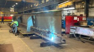


This article shall walk the reader through a concise overview on the design of structural steel plate girders according to EN 1993-1-5:2006, and EN 1993-1-1:2005
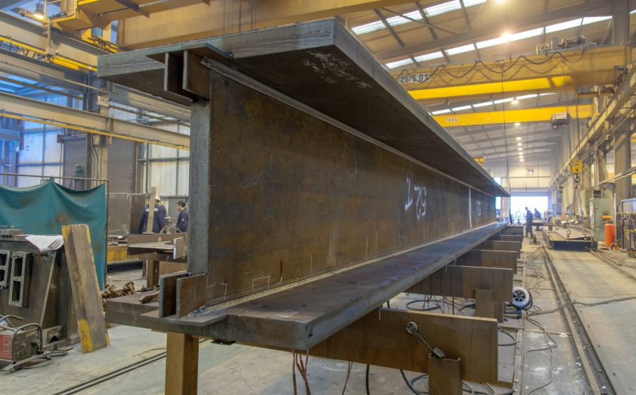
Plate girders are used to span large horizontal distance that cannot be possible when using typical standard rolled sections or hot-finished sections. They are used as girders in supporting bridge decks, in factories for supporting heavy cranes, as transfer structure in buildings, as outriggers in super tall building structures, etc. They are fabricated by welding together of steel plates.
Bases of Plate Girder Design
Plate girders are susceptible to local effects which does not allow the elements to achieve their yield strength before buckling. The stability models in EN 1993-1-5 account for the reduction in resistance due to these local effects. This includes the effective width method for direct stresses (axial and bending), the reduction factor for shear buckling resistance of the web, and the effective length for resistance to transverse forces (patch loading). Furthermore, the standard provides interaction criteria to account for the simultaneous presence of these stress components.
The approach to the design of plate girder to various design effects is further discussed below:
Design of Plate Girders under Bending Moment
The resistance of plate girder in bending is carried out using the expression (6.12) in EN 1993-1-1, which is reproduced below:
$
\,\,\frac{M_{Ed}}{M_{cRd}}\,\,\leqslant \,\,1
$
where Mc,Rd is the design bending resistance and it is determined using expression (6.15) of EN 1993-1-1.
$
\,\,Mc,Rd\,\,=\,\,\frac{W_{eff,min}.\,\,f_y\,\,}{\varUpsilon _{m0}}\,\,\,\,
$
Weff,min is the elastic section modulus of the effective cross-section. This is calculated using the effective widths of the compressed parts of the section on the basis of EN 1993-1-5
Reduced Stress Method
Another alternative to verifying the resistance of a plate girder is using the reduced stress method where the gross section is used but with reduced design strength. The expression for reduced stress method is given below:
$\frac{\sigma_{x, E d}}{\rho^{f_y} / \gamma_{\gamma_{m 1}}} \leq 1$
where;
ρ is the reduction factor for plate buckling.
σx,Ed is the stress calculated using the gross section properties
Flange Resistance Only
Alternative simplification is to assume only the flanges of the section resist the moment and determine the resistance of the section on this basis using the expression below:
$
\,\,M_{f,Rd}\,\,=\,\,\frac{A_{eff}.\,\,f_y\,\,}{\varUpsilon _{m0}}\,\,\,\,
$
This simplification is particularly useful for preliminary sizing, it may also be used for detailed design of the section where there is no patch load. Furthermore, when the girder is designed such that the web is not contributing to bending resistance (i.e.: MEd < Mf,Rd ), it improves the shear capacity of the section.
Design of Plate Girders under Axial Load
Plated structures subject to axial load whether tension or compression should be verified using the expression below from EN 1993-1-1
$
\,\,\frac{N_{Ed}}{N_{Rd}}\,\,\leqslant \,\,1
$
where;
$
N_{Rd}\,\,=\frac{A\,\,f_y}{\gamma _{mo}}\,\,
$ (For tensile resistance)
For compression resistance, the effects of buckling and shear lag has to be accounted for so the resistance is gives as:
$
N_{cRd}\,\,=\frac{A_eff\,\,f_y}{\gamma _{m0}}\,\,
$
Where; Aeff is the effective cross-section area which is to be determined on the basis of EN 1993-1-5
Combined Verification of Axial load and Bending Moment
When the member is subject to combined axial load and bending moment, the resistance verification should be carried out using the expressions below:
For members subject to compression and uniaxial bending
$\eta_1=\frac{N_{E d}}{\frac{f_{y A_{e f f}}}{Y_{m o}}}+\frac{M_{E d}+N_{E d} e y_{,_N}}{\frac{f_{y W_{e f f}}}{Y_{m o}}} \leq 1$
For members subject to compression and biaxial bending
$\eta_1=\frac{N_{E d}}{\frac{f_{y A_{e f f}}}{r_{m o}}}+\frac{M_{E d}+N_{, E d} e y_{, N}}{\frac{f_{y w_{y, e f f}}}{r_{m o}}}+K_{y z} \frac{M_{z, E d}+N_{, E d} e z, N}{\frac{f_{y w_{z, \text { eff }}}}{r_{m o}}} \leq 1$
Design of Plate Girders for Shear Buckling
Design for shear buckling resistance is treated in section 5 of EN 1993-1-5. This section of the standard is applicable provided that the following criteria are met:
- a) the panels are rectangular within the angle limit
- b) stiffeners, if any, are provided in the longitudinal or transverse direction or both
- c) all holes and cut outs are small
- d) members are of uniform cross section.
It is not necessary to verify a plate for shear buckling provided that
$\frac{\boldsymbol{h}_{\boldsymbol{w}}}{\boldsymbol{t}_{\boldsymbol{w}}} \leq \mathbf{7 2} \frac{\varepsilon}{\eta}$ (for web without intermediate stiffeners) (EN 1993-1-1 clause 6.2.6(6)) $\frac{\boldsymbol{h}_{\boldsymbol{w}}}{\boldsymbol{t}_{\boldsymbol{w}}} \leq \frac{\mathbf{3 1}}{\eta} \varepsilon \sqrt{\boldsymbol{k}_{\boldsymbol{T}}}$ (for stiffened web) (EN 1993-1-5 clause 5.1.(2))
If verification of shear buckling is necessary, the plate should be provided with transverse stiffeners at the supports and the resistance of a cross-section of a plate girder should be verified using:
$
\,\,\frac{V_{Ed}}{V_{bRd}}\,\,\leqslant \,\,1
$
The shear buckling resistance (Vb,Rd) is the summation of shear resistance of the web and shear resistance of the flange. This is given in EN 1993-1-5 as:
$V_{b R d}=V_{b w . R d}+V_{b f R d} \leq \frac{\eta f_{y w} h_W t}{\sqrt{3} \gamma_{m 1}}$ (cl 5.2 EN 1993-1-5 Eq. 5.1)
As seen in the above equation, the summation of the flange and web shear resistance must be less than or equals to the shear resistance of the web itself.
η is a term to allow for an increase in fy due to the effect of strain-hardening. The recommended value in EN 1993-1-1 is 1.2 when steel grade ≤ S460, and 1.0 when steel grade ˃ S460. The UK National Annex for EN 1993-1-5: Clause NA.2.4 indicates in that a value of 1.0 should be used for all steel grades
Contribution of the web to Shear Resistance of Plate Girders
The shear resistance from the web can be calculated using the expressions below:
$V_{b w . R d}=\chi_w \frac{f_{y w} \cdot h_W^{\square} t}{\sqrt{3} \Upsilon_{m 1}} \text { (cl } 5.2 \text { EN 1993-1-5 Eq. 5.2) }$
χw can be determined from Table 5.1 of EN 1993-1-5 for plate girder with rigid-end post and non-rigid end post. The table is reproduced below:

λw in table 5.1 can be determined as follows:
For transverse stiffeners at supports only (see figure below):
$$
\lambda_w=\frac{h_w}{86.4 \varepsilon t_w} \quad \text { (EN 1993-1-5 Eq. 5.6) }
$$
For transverse stiffeners at supports and intermediate transverse or longitudinal stiffeners or both
$$
\lambda_w=\frac{h_w}{37.4 \varepsilon t_{w \sqrt{K_T}}}
$$
KT should be determined based on the following:
$$
\begin{aligned}
& \frac{a}{h_w} \geq 1 ; k_t=5.34+4.0\left(\frac{h_w}{a}\right) 2+K_{r s l} \\
& \frac{a}{h_w}<1 ; k_t=4.0+5.34\left(\frac{h_w}{a}\right) 2+K_{r s l}
\end{aligned}
$$
$K_{r s l}$ can be conservatively taken as 0 (this assumes there are no intermediate stiffeners)
Contribution of the flange to Shear Resistance of a plate girder
The shear resistance from the flange can be calculated using the expressions below:
$\begin{aligned} & V_{b f R d}=\frac{b_f t_f^2 f_{y f}}{c \Upsilon_{m 1}}\left[1-\left(\frac{M_{E d}}{M_{f R d}}\right)^2\right] \quad(\mathrm{cl} 5.4 \text { EC3-5 Eq. 5.8) } \\ & \mathrm{C}=\mathrm{a}\left(0.25+\frac{1.6 b_f t_f^2 f_{y f}}{t_w h_w f_{y w}}\right)\end{aligned}$
Mf,Rd is the moment of resistance of the cross section consisting of the effective area of the flanges only
The effective width of the flange for shear bf, is limited as shown below:
bf = 2 x 15 x ε x tf + tw
The equation above can be rewritten as:
$\begin{aligned} & V_{b f R d}=\chi_f \frac{f_{y w} \cdot h_w t}{\sqrt{3} \Upsilon_{m 1}} \\ & \text { So that } \chi_f \text { becomes } \frac{\sqrt{3}}{t_w h_w f y_w} \frac{b_f t_f^2 f_{y f}}{c \Upsilon_{m 1}}\left[1-\left(\frac{M_{E d}}{M_{f R d}}\right)^2\right]\end{aligned}$
This makes the equation of Vbf,Rd be structurally similar to Vbw,Rd
Design of Plate Girder’s Web for Resistance to transverse force (Patch Loading)
The web of a plate girder under concentrated or patch loads tend to fail by either bearing or buckling. Any of these failures occur as a result of a concentrated vertical force (patch load from a wheel or a column, etc.) pushing directly onto a small area of the flange.
Web bearing is a localized failure of the web by either crushing without buckling, or by crippling which is a localized folding of the web. On the other hand, web buckling is an out-of-plane deformation over most of the web depth which makes the web to bulge out as if a column buckle
The design of plated girders to resist transverse forces is covered in section 6 of EN 1993-1-5 provided that the compression flange is adequately restrained in lateral direction.
Resistance to transverse forces (patch loading) should be verified using the expression below:
η2 = FEd/ FRd ≤ 1
$F_{R d}=\frac{f_{y w} L_{e f f} t_w}{\Upsilon_{m 1}}$ (EN 1993-1-5: Equ 6.1)
Where;
fyw is the yield strength of the web
Leff is the effective loaded length for resistance to transverse forces, i.e. Leff = χF ly,
ly is the effective loaded length appropriate to the length of stiff bearing Ss
χF is a reduction factor.
Each of these parameters shall be discussed further below:
Application of Patch load and Buckling factor (KF)
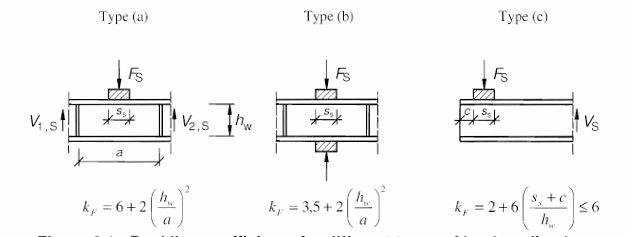
The point of application of the patch load on a member significantly determines its buckling coefficient (KF) which accounts for the boundary conditions around the point of load application. The buckling coefficient is a key parameter in determining the elastic critical load (Fcr)
The standard gives three cases that defines how the patch load is applied
- Type a: The patch load is applied at a significant distance from the member ends. This can be model as a patch load applied at mid-span or somewhere close to the mid-span far from supports. In such a case, the load is resisted by shear forces in the web, (see Type (a))
- Type b: The patch load is applied at a point where an opposing concentrated load is also acting on the section. This typically model a scenario where concentrated load is applied at the section of a member over support. In such a case, the load is applied through one flange and transferred through the web directly to the other flange, (see Type (b)).
- Type C: The patch load is applied at or close to a free or unstiffened end. This typically model a case where concentrated load is applied at the free end of a cantilever or at the end support of a beam without end stiffeners. (see Type (c)).
Length of Stiff Bearing (Ss)
According to clause 6.3(1) of EN 1993-1-5, the length of stiff bearing s, on the flange should be taken as the distance over which the applied load is effectively distributed at a slope of 1:1 (45degree). However, s should not be taken as larger than hw.

Effective Loaded length (ly) of length appropriate to the Stiff Bearing
For load application type (a) and type (b)
$\mathrm{Iy}=s_s+2 t_f\left(\mathrm{I}+\sqrt{m_1+m_2}\right.$ but $\mathrm{Iy} \leq$ distance between adjacent transverse stiffeners (a)
for type (c) ly should be taken as the smaller of
$$
\begin{aligned}
& \mathrm{ly}=\mathrm{le}+t_f \sqrt{\frac{m_1}{2}+\left(\frac{l_e}{t_f}\right)+m_2} \\
& \mathrm{ly}=\mathrm{le}+t_f \sqrt{m_1+m_2} \\
& \mathrm{le}=\frac{K_y E t_w^2}{2 f_{y w} h_w} \leq s_s+\mathrm{c}
\end{aligned}
$$
Reduction Factor (χF) for Effective Length of Resistance (Leff)
$\begin{aligned} & \chi_F=\frac{0.5}{\lambda_F} \leq 1 \\ & \lambda_F=\sqrt{\frac{t_w l_y f_{y w}}{F_{c r}}} \\ & F_{c r}=0.9 K_f \mathrm{E} \frac{t_w^3}{h_w}\end{aligned}$
Resistance of Transverse Stiffeners
The web stiffeners are to be verified for axial resistance and buckling resistance
Axial Resistance of Stiffeners
The axial resistance of a stiffener should be verified using:
$
\,\,\frac{N_{Ed}}{N_{Rd,s}}\,\,\leqslant \,\,1
$
Axial load on the stiffener is determined as follows
$$
\begin{aligned}
& N_{E d}=V_{E d}-V_{b w, R d} \\
& V_{b w, R d}=\chi_w \frac{f_{y w} \cdot h_w^{\square} t}{\sqrt{3} Y_{m 1}} \text { (as explained above) }
\end{aligned}
$$
Axial Resistance of the stiffener $N_{R d}$ is determined as follows
$$
\begin{aligned}
& N_{R d}=\frac{A_s f_{y z}}{\gamma_{m o}} \\
& A_s=2 b_s t_s
\end{aligned}
$$
Buckling Resistance of Stiffeners
The buckling resistance of the stiffener is determined in accordance with EN 19931-1: Clause 6.3 like for typical compression members. The buckling resistance should satisfy the expression below:
$$
\frac{N_{E d}}{N_{b R d}}=\leq 1
$$
Where;
$N_{E d}$ is the design axial load
$N_{b R d}$ is the design buckling resistance of the stiffeners
$$
\begin{aligned}
& N_{b R d}=\chi \frac{\text { Aequiv.fy }}{\Upsilon_{m 1}} \\
& \text { Aequiv }=A_{s t}+30 \varepsilon t^2 \\
& A_{s t}=\left(2 b_s+t_w\right) t_s
\end{aligned}
$$
$\chi$ is the reduction factor
The reduction factor is determined the same way as for compression members
The value of the reduction factor can be read off from the buckling curve given in figure 6.4 of the standard having determined the slenderness. Table 6.2 of the standard enables designers to determine the appropriate buckling curve for flexural buckling and other buckling modes for compression members. Alternatively, the reduction factor can be evaluated using the expression below.
$\begin{aligned} & \chi=\frac{1}{\phi+\sqrt{\phi^2-\lambda^2}} \leq 1 \\ & \left.\phi=0.5\left(1+\underline{\underline{\alpha( } \lambda^{\square}}-0.2\right)+\lambda^2\right)\end{aligned}$
α is an imperfection factor and it is given in Table 6.1 of the standard (It should be noted that table 6.1 can only be consulted after determining the appropriate buckling curve using table 6.2)
λ is the non-dimension slenderness. This depends on the buckling mode concerned. Expression to evaluate non-dimension slenderness is gives as follows
$\begin{aligned} & \boldsymbol{\lambda}=\sqrt{\frac{A \cdot f_y}{N_{c r}}}=\frac{\boldsymbol{L}_{c r}}{i} \frac{\mathbf{1}}{\lambda_{\mathbf{1}}} \text { for class } 1,2, \text { and } 3 \mathrm{cr} \\ & \mathrm{Lcr}=0.75 \mathrm{hw} \\ & \mathrm{i}=\text { radius of gyration about the relevant } \\ & \boldsymbol{\lambda}_{\mathbf{1}}=\boldsymbol{\pi} \sqrt{\frac{\boldsymbol{E}}{\boldsymbol{f}_y}}=\mathbf{9 3 . 9} \\ & \boldsymbol{\lambda}=\sqrt{\frac{\text { Aeqiv.fy }}{N_{c r}}} \text { for class } \mathbf{4} \text { cross-sections } \\ & N_{c r}=\frac{\pi^2 E \text { lequiv }}{l^2} \\ & \text { lequiv }=l_{s t}+1 / 1230 \varepsilon t^4 \\ & l_{s t}=\frac{t_s\left(2 b_s+t_w\right)^3}{12}\end{aligned}$
Lcr is the buckling length in the plane being considered.
Ncr is the elastic critical force for the relevant buckling mode based on gross cross-section properties
i is the radius of gyration about the relevant axis.
Design of Plate Girder for Flange Induced Buckling
Flange induced buckling is a failure where the compression flange of a slender girder buckles vertically into a web. This occurs when the web is too thin to provide enough restraint to the flange as it tries to buckle under longitudinal compression. For the web to be able to provide enough restraint, the expression below must be satisfied:
$\frac{h_w}{t_w} \leq \mathrm{k} \frac{E}{f_{y f}} \sqrt{\frac{A_w}{A_{f c}}}$
The value of the factor k should be taken as follows:
plastic rotation utilized k = 0,3
plastic moment resistance utilized k = 0,4
elastic moment resistance utilized k = 0,55
fyf is taken as the yield strength of the flange under compression
Afc is the gross area of the flange under compression
When the expression is not satisfied, the web has to be thickened until the desired result is achieved.
The Interaction
The design of plated structural elements requires checking for the interaction of different types of stresses. There are primarily two main interaction verifications you must perform to ensure the plate does not fail under combined stresses.
The Interaction between Shear Force, Bending Moment and Axial Force
This is the most critical check for the web of a plate girder. While the flanges primarily resist bending, the web resists shear. In regions where both are high (like near a support), the web must be checked for the interaction of the transverse shear force and the longitudinal stresses.
Provided that η3 (see below) does not exceed 0.5, the design resistance to bending moment and axial force need not be reduced to allow for the shear force. If η3 is more than 0.5 the combined effects of bending and shear in the web of a plated girder should satisfy:
$\eta_1+\left(1-\frac{M_{f, R d}}{M_{p l, R d}}\right)\left(2 \eta_3-1\right) \leq 1.0$ for $\eta_1 \geq \frac{M_{f, R d}}{M_{p l, R d}}$
Mf,Rd is the design plastic moment of resistance of the section consisting of the effective area of the flanges;
Mpl,Rd is the design plastic resistance of the cross section consisting of the effective area of the flanges and the fully effective web irrespective of its section class.
η1 = $
\,\,\frac{M_{Ed}}{M_{pl,Rd}}\,\,\leqslant \,\,1
$
η3 = $
\,\,\frac{V_{Ed}}{V_{bw,Rd}}\,\,\leqslant \,\,1
$
Interaction between Transverse Force (patch loading), Bending Moment and Axial Force
If a concentrated transverse load is applied to a flange in a region where the plate is already under longitudinal stress (Bending or Axial force), a third interaction check is required. This prevents the local buckling of the web under the combined effect of crushing from the patch load and buckling from the bending.
The interaction between transverse load, bending and axial force should be verified using expression (7.2) of the standard which is reproduced below:
η2 ≤ 0.8 η1 ≤ 1.4
η2 = $
\,\,\frac{F_{Ed}}{F_{Rd}}\,\,\leqslant \,\,1
$
η1 = $
\,\,\frac{M_{Ed}}{M_{pl,Rd}}\,\,\leqslant \,\,1
$
Member Verification
Plate girders are also to be verified for member stability such as flexural buckling and lateral torsional buckling. These however are to be carried out according to EN 1993-1-1, but the effective cross-section properties such leff, Weff, Aeff determined according to EN 1993-1-5 should be used. For more information about lateral torsional buckling and flexural buckling, read: