


This article presents a worked example on how to calculate the deflection of a reinforced concrete beam using the rigorous calculation method of cl 7.4.3 in EN 1992-1-1. The beam which deflection is to be checked has already being designed here as a singly reinforced concrete beam. In that article, the beam was designed for flexural and shear strength, and then deflection check was carried out using the deemed-to-satisfy span-effective-depth ratio method. In this article, we shall carry out the deflection check using the calculation method.
Beam Design Details
The dimension and the reinforcement details from strength design are given thus:
Beam Dimensions
Beam breadth: 225mm
Beam Depth: 450mm
Beam Length: 5000mm
Reinforcement Details
Beam type: Singly reinforced
Provided Area of tensile reinforcement: 599.8mm2
Required Area of tensile reinforcement: 440.9mm2
Loading
For deflection check, serviceability quasi-permanent load should be use. The moment due to quasi-permanent load is derived below
Characteristic Permanent Load (gk): 10.42KN/m
Characteristic Variable Load (qk): 6.25KN/m
Quasi-Permanent Factor (ψ2) = 0.3 (Category A/B Buildings)
Design Quasi-Permanent Line Load: 10.42 + (0.3 x 6.25) = 12.30kN/m
\text { Quasi-Permanent Moment }=\frac{12.3 \times 5^2}{8}=38.42 \mathrm{KNm}Quasi-Permanent Moment = = 38.42KNm
Cement type and exposure conditions
Cement Class: Class N
Exposure condition: Two short sides & one long side exposed
Relative humidity: 80%
Deflection Check
The calculations of deflection check reproduced below was carried out using fppSuite software. You can download the pdf report which is directly from fppSuite here. To also use fppSuite for your structural designs and calculations, click here
Below are the detailed deflection check using calculation method:
- EXPOSED PERIMETER, U
u= TWO SHORT SIDES + ONE LONG SIDE EXPOSED
u = 2b + h
u = 900.0 mm
2. CROSS-SECTIONAL AREA, Ac
Ac = b × h = 225.0 × 450.0
Ac = 101250 mm²
3. NOTIONAL SIZE,
h0 = 2 . Ac / u = 2 × 101250 / 900.0
h0 = 225.0 mm
4. Shrinkage Strain
MEAN CONCRETE STRENGTH, fcm
fcm = fck + 8 = 30.0 + 8 = 38N/mm²
BASIC DRYING SHRINKAGE COEFFICIENT, εcdo ANNEX B,
For CEMENT CLASS N → αds1 = 4, αds2 = 0.12
εcdo = 0.85 × [(220 + 110αds1 ) × exp(−αds2 × 0.1 × fcm)] × 1.55 × [1 − (0.01RH)³] × 10−6 (Cl. 3.1.4, Annex B )
εcdo = 0.85 × [(220 + 110 × 4) × exp(−0.12 × 0.1 × 38.0)] × 1.55 × [1 − (0.01 × 80.0)³] × 10−6
εcdo = 0.00026895
NOTIONAL SIZE COEFFICIENT, TABLE 3.3
h0 = 225.0 mm → 200 < h0 ≤ 300 mm → h0 = 0.75
h0 = 0.75
DRYING SHRINKAGE STRAIN, εcd
εcd = εcdo × kh = 0.00026895 × 0.75
εcd = 0.00020171
AUTOGENOUS SHRINKAGE STRAIN, εca(∞)
εca = 2.5 × (fck − 10) × 10−6
εca = 2.5 × (30.0 − 10) × 10−6
εca = 5e-05
TOTAL SHRINKAGE STRAIN, εcs
εcs = εcd + εca = 0.00020171 + 5e-05
εcs = 0.00025171
5. Creep Coefficient
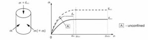
fcm = 38.0 N/mm² > 35 N/mm² → high-strength correction factors α1 , α2 apply.
HIGH-STRENGTH CORRECTION FACTORS
α1 = (35/fcm)0.7 = (35/38.0)^0.7 = 0.9441
α2 = (35/fcm)0.2 = (35/38.0)^0.2 = 0.9837
RELATIVE HUMIDITY FACTOR, ΦRH
ΦRH = [1 + (1 − 0.01RH)/ (0.1 × h0 x 0.333) × α1] × α2
ΦRH = [1 + (1 − 0.01 × 80.0)/ (0.1 × 225.00.333) × 0.9441] × 0.9837
ΦRH = 1.2896
ADJUSTED AGE AT LOADING,
T0 CEMENT CLASS EXPONENT
α = 0
t0 = t0,T × [9/(2 + t0,T x 1.2) + 1]^ α
t0 = 28 × [9/(2 + 28 x 1.2) + 1] ^ 0
t0 = 28.0 days
Deflection assessed at t = ∞ → βc (t,t 0 ) = 1.00 (full long-term creep development).
CREEP COEFFICIENT, φ(t,t0)
φ(t,t0) = ΦRH × [16.8 / √fcm] × [1 / (0.1 + t0 0.2)] × βc(t,t0)
φ(t,t0) = 1.2896 × [16.8 / √38.0] × [1 / (0.1 + 28.00.2)] × 1
φ(t,t0) = 1.7167
6. Effective Modulus of Elasticity
MEAN SECANT MODULUS AT 28 DAYS, Ecm,28 (Annex B.1 Cl. 3.1.3, Table 3.1 & Cl. 7.4.3(5))
Ecm,28 = 22 × [(fck + 8)/10]0.3 = 22 × [(30.0 + 8)/10]0.3
Ecm,28 = 32.84 GPa (kN/mm²)
Age at loading t0,T = 28 days → no strength-gain adjustment required, Ecm = Ecm,28
EFFECTIVE MODULUS OF ELASTICITY, Ec,eff EQ. 7.20
Ec,eff = Ecm/ (1 + φ(t,t0)) = 32.84 / (1 + 1.7167)
Ec,eff = 12.09 GPa (kN/mm²)
7. Modular Ratio
SHORT-TERM (ELASTIC) MODULAR RATIO, αe
αe = Es / Ecm = 200 / 32.84
αe = 6.091
LONG-TERM (EFFECTIVE) MODULAR RATIO, αe,LT
αe,LT = Es / Ec,eff = 200 / 12.09
αe,LT = 16.547
8. Cracking Moment & Distribution Coefficient
MEAN TENSILE STRENGTH, fctm
fctm= 0.3 × fck 2/3
fctm = 0.3 × 30.0 x 2/3
fctm = 2.896 N/mm²
CRACKING MOMENT, Mcr
Mcr = fctm × (b × h²) / 6 × 10⁻⁶
Mcr = 2.896 × (225.0 × 450.0²) / 6 × 10⁻⁶
Mcr = 21.995 kNm
M = 38.42 kNm > Mcr = 21.995 kNm → SECTION CRACKED UNDER SERVICE MOMENT
DISTRIBUTION COEFFICIENT (SHORT-TERM), ζ
Β = 1.0
ζ = max[0, 1 − β × ( Mcr /M)²] = max[0, 1 − 1 × (21.995/38.42)²]
ζ = 0.6723
DISTRIBUTION COEFFICIENT (LONG-TERM),
Β = 0.5 (SUSTAINED/CYCLIC LOADING)
ζLT = max[0, 1 − β × (Mcr/M)²] = max[0, 1 − 0.5 × (21.995/38.42)²]
ζLT = 0.8361
9. Second Moment of Area
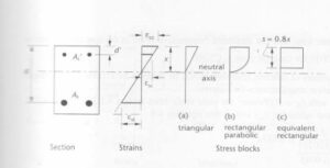
Cracked Neutral Axis depth (SHORT-TERM)
x = [−αe As + √((αe As)² + 2 b αe As d)] / b
x = [−6.091 × 599.8 + √((6.091 × 599.8)² + 2 × 225.0 × 6.091 × 599.8 × 407.0)] / 225.0
x = 99.87 mm
CRACKED SECOND MOMENT OF AREA, Icr (SHORT-TERM)
Icr = (b × x³)/3 + αe × As × (d − x) ²
Icr = (225.0 × 99.87³)/3 + 6.091 × 599.8 × (407.0 − 99.87)²
Icr = 419314151 mm⁴
CRACKED NEUTRAL AXIS DEPTH, xLT (LONG-TERM)
xLT = [−αe,LT As + √((αe,LT As)² + 2 b αe,LT As d)] / b
xLT = 150.44 mm
CRACKED SECOND MOMENT OF AREA, ICR,LT (LONG-TERM)
Icr,LT = (b × xLT³)/3 + αe,LT × As × (d − xLT)²
Icr,LT = 908637835mm⁴
UNCRACKED (GROSS) SECOND MOMENT OF AREA, IUNCR
IUNCR = b × h³ / 12 = 225.0 × 450.0³ / 12
IUNCR = 1708593750 mm⁴
10. Curvature Due to Loading
CRACKED CURVATURE, (1/r)cr — SHORT-TERM & LONG-TERM
(1/r)cr = M × 106 / (Ecm × 103 × Icr)
(1/r)cr = 38.42 × 10⁶ / (32.84 × 103 × 419314151)
(1/r)cr = 2.79e-06 mm−1
(1/r)cr,LT = M × 106 / (Ec,eff × 103 × Icr,LT)
(1/r)cr,LT = 38.42 × 10⁶ / (12.09 × 103 × 908637835)
(1/r)cr,LT = 3.498e-06 mm−1
UNCRACKED CURVATURE, (1/r)uncr — SHORT-TERM & LONG-TERM
(1/r)uncr = M × 106 / (Ecm × 103 × I,uncr)
(1/r)uncr = 38.42 × 10⁶ / (32.84 × 103 × 1708593750)
(1/r)uncr = 6.85e-07 mm−1
(1/r)uncr,LT = M × 106 / (Ec,eff × 103 × Iuncr)
(1/r)uncr,LT = 38.42 × 10⁶ / (12.09 × 103 × 1708593750)
(1/r)uncr,LT = 1.86e-06 mm−1
INTERPOLATED (LOADING) CURVATURE, (1/r)m
(1/r)m = ξ (1/r)cr + (1 − ξ) (1/r)uncr
(1/r)m = 0.6723 × 2.79e-06 + (1 − 0.6723) × 6.85e-07
(1/r)m,LT = ζLT (1/r)cr,LT + (1 − ζLT) (1/r)uncr
(1/r)m,LT = 0.8361 × 3.498e-06 + (1 − 0.8361) × 1.86e-06
(1/r)m,LT = 3.23e-06 mm−1
11. Curvature due to Shrinkage
FIRST MOMENT OF REINFORCEMENT AREA ABOUT CENTROID, Scr
Instantaneous cracked section
Scr = As × (d − x)
Scr = 599.8 × (407.0 − 99.87)
Scr = 184218 mm³
Long-term cracked section
Scr,LT = As × (d − xLT)
Scr,LT = 599.8 × (407.0 − 150.44)
Scr,LT = 153882 mm³
Uncracked Section
Suncr = As × (d − h/2)
Suncr = 599.8 × (407.0 − 450.0/2)
Suncr = 109164 mm³
CRACKED SHRINKAGE CURVATURE, (1/RCS)CR
(1/rcs)cr = Scr × αe × Scr/ Icr
(1/rcs)cr = 0.00025171 × 6.091 × 184218 / 419314151
(1/rcs)cr = 6.74e-07 mm−1
(1/rcs)cr,LT = Scr,LT × αe,LT × Scr,LT / Icr,LT
(1/rcs)cr,LT = 0.00025171 × 16.547 × 153882 / 908637835
(1/rcs)cr,LT = 7.05e-07 mm−1
UNCRACKED SHRINKAGE CURVATURE, (1/RCS)UNCR
(1/rcs)uncr = εcs × αe × Suncr / Iuncr
(1/rcs)uncr = 0.00025171 × 6.091 × 109164 / 1708593750
(1/rcs)uncr = 9.8e-08 mm−1
(1/rcs)uncr,LT = εcs × αeLT × Suncr / Iuncr
(1/rcs)uncr,LT = 0.00025171 × 16.547 × 109164 / 1708593750
(1/rcs)uncr,LT = 2.66e-07 mm−1
INTERPOLATED SHRINKAGE CURVATURE, (1/RCS)
(1/rcs) = ζ × (1/rcs)cr + (1 − ζ) × (1/rcs)uncr (1/rcs)
(1/rcs) = 0.6723 × 6.74e-07 + (1 − 0.6723) × 9.8e-08
(1/rcs) = 4.85e-07 mm−1
(1/rcs,LT) = 0.8361 × 7.05e-07 + (1 − 0.8361) × 2.66e-07
(1/rcs,LT) = 6.33e-07 mm−1
Total Curvature (Loading & Shrinkage)
(1/r)total = (1/r)M + (1/rcs)
(1/r)total = 2.1e-06 + 4.85e-07
(1/r)total = 2.585e-06 mm−1
(1/r)total,LT = (1/r)M,LT + (1/rcs,LT)
(1/r)total,LT = 3.23e-06 + 6.33e-07
(1/r)total,LT = 3.863e-06 mm−1
12. DEFLECTION COEFFICIENT, K
STRUCTURAL SYSTEM: SIMPLY SUPPORTED, k = 0.104
INSTANTANEOUS (SHORT-TERM) DEFLECTION, a
a = k × L² × (1/r)total
a = 0.104 × 5000.0² × 2.585e-06
a = 6.72 mm
LONG-TERM DEFLECTION, aLT
aLT = k × L² × (1/r)total,LT
aLT = 0.104 × 5000.0² × 3.863e-06
aLT = 10.04 mm
Deflection Check
LIMITING DEFLECTION, alim
alim = L/250 = 5000.0 / 250
alim = 20.0 mm
Instantaneous deflection a = 6.72 mm vs alim = 20.0 mm, deflection passed
Long-term deflection aLT = 10.04 mm vs alim = 20.0 mm, deflection passed


2 Comments