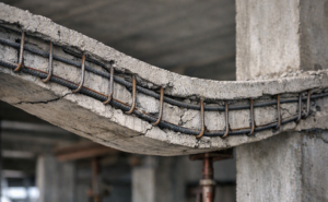


Deflection is an important serviceability criterion in the design of structures. Excessive deflection can compromise aesthetic, give impression of an unsafe structure, cause damage to brittle finishes, cause problem to fixtures etc. Ensuring deflection limit is not exceeded is one of the important criteria of structural designs.
The deformation of a member or structure shall not be such that it adversely affects its proper functioning or appearance. Appropriate limiting values of deflection taking into account the nature of the structure, of the finishes, partitions and fixings, should be established. In some cases, strigent limitation may be required to ensure the proper functioning of machinery such as cranes or apparatus supported by the structure, or to avoid ponding on flat roofs.
Instantaneous Deflection and Long-term Deflection
Instantaneous Deflection: This is the initial deformation of a structural member which happens immediately upon the first application of load. The load may be externally imposed, or its own self-weight which it is forced to support upon the stripping of supporting formworks. This deflection is elastic in nature as it does not include time-dependent effects such as creep and shrinkage.
Long-term Deflection: Long‑term deflection is the gradual, time‑dependent deformation of structural members such as reinforced concrete beams and slabs under sustained loads, primarily caused by creep, shrinkage, and other material or environmental effects. It is distinct from short‑term deflection, which occurs immediately after loading.
Approach of EN 1992-1-1 to Deflection
The standard (EN 1992-1-1) has two approaches to ensuring deflection does not exceed permissible limit
- Limiting the span/depth ratio, according to 7.4.2
- Comparing a calculated deflection, according to 7.4.3, with a limit value
Limiting Span-to-depth ratio (Deemed-to-satisfy approach)
A simple approach to designing against excessive deflection of a member is limiting its span/depth ratio. The logic behind this is by limiting the span-to-depth ratio, the member is prevented from being slender such that it suffers excessive deflection. This approach ordinarily does not intend to determine the actual deflection of the member under consideration but to ensure the member is stiff enough such that its deflection is within acceptable limit.
Using this method, the span-to-depth ratio is compared against limiting values given in expression 7.16.a and 7.16.b of the standard. The expressions are given below:
$$
\begin{aligned}
& \frac{l}{d}=\mathrm{K}\left[11+1.5 \sqrt{f_{c k}} \frac{\rho^0}{\rho}+3.2 \sqrt{f_{c k}}\left(\frac{\rho^0}{\rho}-1\right)^{3 / 2}\right] \text { If } \rho \leq \rho_o \\
& \frac{l}{d}=\mathrm{K}\left[11+1.5 \sqrt{f_{c k}} \frac{\rho^0}{\rho-\rho^{\prime}}+\frac{1}{12} \sqrt{f_{c k}} \sqrt{\frac{\rho^{\prime}}{\rho^0}}\right] \text { If } \rho>\rho_o
\end{aligned}
$$
where;
k is the factor accounting for the structural system $\rho 0$ is the reference reinforcement ratio $\rho$ is the required tension reinforcement ratio at mid-span to resist the moment due to the design loads (at support for cantilevers), $\rho^{\prime}$ is the required compression reinforcement ratio at mid-span to resist the moment due to the design loads (at support for cantilevers).
When the span-to-depth ratio falls below the limiting value, the deflection criterion is deemed to have been met. This approach is popularly tagged the deemed-to-satisfy method.
Modification factors
Under this approach, the limiting span-to-depth ratio can be corrected to allow for necessary parameters such as percentage of reinforcement, cross-section dimensions, spans, etc., by multiplying with certain modification factors. The modification factors are discussed below:
- F1 is a modification factor that is dependent on steel stress and percentage or amount of tensile reinforcement. It is the ratio of the assumed stress (310MPa) and the actual service stress (i.e: 310/ ss). ss is tensile stress in reinforcement at mid-span (at support for cantilevers) under design load at SLS.
As a simplification, the ratio of the base stress and actual service can be taken as 500 As,prov/(fykAs,req)
- F2 is a modifying factor for flanged sections where the ratio of the flange breadth to the rib breadth exceeds a value of 3
When beff/bw = 1.0, factor F2 = 1.0. When beff/bw is greater than 3.0, factor F2 = 0.80. For values of beff/bw between 1.0 and 3.0, interpolation may be used
- F3 is the long span modification factor. This is applied prevent damage to brittle finish in long spanning members It should be determined as follows
a) in flat slabs in which the longer span is greater than 8.5 m, F3 = 8.5/leff
b) in beams and other slabs with spans in excess of 7.0 m, F3 = 7.0/leff
F1, F2, and F3 as labels are not part of Eurocode 2 itself, they are teaching conventions adopted for clarity and learning.
Calculated Deflection
The calculated deflection approach given in 7.4.3 of EN 1992-1-1 seeks to capture the actual behaviour of a structural member under relevant loads between a fully cracked and uncracked state. The mathematical model is given in expression (7.18) as:
∝ = Ϛ ∝ 11 + (1 – Ϛ)∝ 1
∝ is the deformation parameter being considered which may be, for example, a strain, a curvature, or a rotation depending on context.
∝ 11 and ∝ 1 are the deformation parameters calculated for uncracked and fully cracked conditions respectively
Ϛ is the distribution coefficient which is used to interpolate between the cracked and uncracked state. It accounts for stiffening effects of concrete between cracks. After cracking, concrete between cracks still carries some tension which increases the effective stiffness of the section as against a fully cracked model. It can be calculated using the below expression
$\zeta=1-\beta\left(\frac{\sigma_{s r}}{\sigma_s}\right)^2$
Ϛ = 0 for uncracked sections
β is a coefficient taking account of the influence of the duration of the loading or of repeated loading on the average strain
= 1.0 for single short-term loading
= 0.5 for sustained load or many circles of repeated loading
σs is the stress in the tension reinforcement calculated on the basis of a cracked section.
σsr is the stress in the tension reinforcement calculated on the basis of a cracked section under the loading conditions causing first cracking
$\frac{\sigma_{s r}}{\sigma_s}$ may be replaced by $\frac{M_{c r}}{M}$ for flexure and $\frac{N_{c r}}{N}$ for pure tension
Shrinkage Induced Deformation
Besides load induced deformation discussed above, EN 1992-1-1 also gives Expression 7.21 to determine shrinkage induced deformation represented as curvature. The expression for shrinkage curvature is given below:
$$
\frac{1}{r_{C S}}=\sum_{c S} \propto_e \frac{S}{I}
$$
where;
$\frac{1}{r_{C S}}$ is the curvature due to shrinkage
$\mathcal{E}_{c s}$ is the free shrinkage strain
$S$ is the first moment of area about the centroid of the section
I is the second moment area of the section
$\propto_e$ is the effective modular ratio (ie $: \propto_e=E_s / E_{c, e f f}$ )
The shrinkage curvature for both cracked and uncracked states should be determined and expression 7.18 discussed previously above should be used to interpolate between them and obtain the average shrinkage curvature.
Application of Calculated Approach
The most rigorous way to assess deflections using the calculation method discussed above is to determine the curvature at multiple points along the member and then obtain the deflection through numerical integration. In this approach, the load‑induced curvature is combined with the shrinkage‑induced curvature, each evaluated by considering both the cracked and uncracked states of the section. By summing these curvatures across different sections and performing numerical integration, the overall deflection of the member is derived.
The total curvature at each section is thus:
\begin{aligned}
& \propto_{\text {loading curvature }}=\zeta \propto_{\text {uncracked loading curv }}+(1-\zeta) \propto_{\text {cracked loading curv }} \\
& \propto_{\text {shrinkage curvature }}=\zeta \propto_{\text {uncracked shrinkage curv }}+(1-\zeta) \propto_{\text {cracked shrinkage curv }} \\
& \propto_{\text {total }}=\propto_{\text {loading curvature }}+\propto_{\text {shrinkage curvature }}
\end{aligned}
Cracked and Uncracked Condition
When computing section properties such as the second moment of area (I) and the first moment of area (S), it is essential to evaluate them separately for both the cracked and uncracked states of the section. This distinction applies to the calculation of both load‑induced curvature and shrinkage‑induced curvature, ensuring that the analysis accurately reflects the different stiffness characteristics of the member under varying conditions. In fact, the separate determination of these properties for cracked and uncracked states is what fundamentally distinguishes the two conditions, making the analysis sensitive to the real behaviour of reinforced concrete members.
Instantaneous and Long-term Curvature
Both instantaneous and long‑term curvatures can be evaluated using the calculation method described above. The procedure involves computing the load‑induced curvature and the shrinkage‑induced curvature, then extrapolating each to obtain their respective average values. These average curvatures are subsequently combined to determine the overall curvature of the member. The distinction lies in the parameters adopted: for instantaneous curvature, the modulus of elasticity of concrete, Ecm, is used and the factor β in the expression for Ϛ is taken as 1; whereas for long‑term curvature, the effective modulus Ec,eff is applied and β is taken as 0.5.
Simplified Method of Deflection Calculation from Curvature
Rather than integrating the curvature at different points to determine the deflection of the member, it can be calculated using the below expression below:
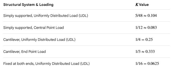
Deflection $=\mathrm{k} \times L^2 \times \propto$
Where;
∝ is the total curvature
L is member length
K is the coefficient that account for structural configuration of the member. The value of K is given below for different system
Click here to study a Worked Example of deflection check using the rigorous calculation method