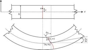


Continuous beams are a cornerstone of structural engineering, often appearing in bridges, frames, and building systems. Their analysis has long been a benchmark for validating both classical methods and modern software. In this article, we revisit a three‑span continuous beam problem. It was first solved by hand using the moment distribution method, then checked against STAAD Pro, and now extended to fppSuite Software. By comparing results across these three approaches, we demonstrate how fppSuite aligns with established theory and industry practice, reinforcing its role as a trusted companion for engineers
The Problem
We shall analyse a 3-span continuous beam shown below using fppSuite, STAAD Pro and manual calculation, and then compare results

STAAD PRO Analysis
STAAD Pro Model
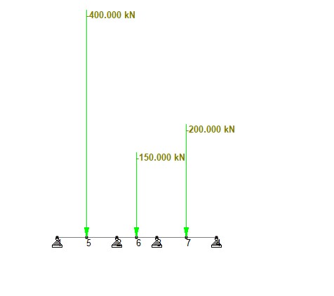
The continuous beam is modeled in STAAD Pro. The beam is assigned a section geometry of 225 x 450mm and the material is chosen as concrete so that the program can compute the second moment area and determine deformation properties like elastic modulus. A pin supports is assigned to node A, B, C, and D; while 400KN, 150KN and 200KN loads are assigned as nodal loads in the middle of beam AB, BC, and CD respectively. An analytical model of the beam is shown below
STAAD Pro Analysis Results


fppSuite Analysis
fppSuite Model
The continuous beam is modeled in fppSuite using the beam tool under Analysis and Modelling Section. The beam section of geometry 225 x 450mm is modelled in Section Studio and loaded into the beam analysis tool. Material is set as concrete under the material tab and the elastic modulus is set as preset. A pin supports is assigned to node A, B, C, and D under the support tab. Under load tab, 400KN, 150KN and 200KN loads are assigned as point loads in the middle of beam AB, BC, and CD respectively. The analytical model, and the bending moment and shear force diagram of the beam analysis is shown below.

Hand Calculation
The hand analysis of the continuous beam is carried out carried out using moment-distribution to determine the supports moments. Thereafter the supports’ reactions and the span moments are evaluated using statics. For full hand calculation, read “Analysis of Span moments of Continuous Beam – Worked Example”.

Bending Moment Diagram from Hand Calculation

Shear Force Diagram from Hand Calculation
Comparison Tables
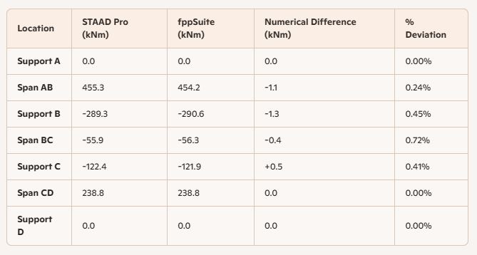
Below is a table showing a comparison between STAAD Pro’s and fppSuite’s results

Discussion
The comparative analysis of the three‑span continuous beam across hand calculation, STAAD Pro, and fppSuite reveals a high degree of consistency, with deviations below 1% across all critical points. This discussion highlights the key observations for both bending moment and shear force results.
Bending Moment Comparison
At the critical span and support locations, STAAD Pro and fppSuite differ by only 0.4–1.3 kNm. For example, at Support B, STAAD Pro reports ‑289.3 kNm while fppSuite gives ‑290.6 kNm, which is a difference of 1.3 kNm. These differences translate to less than 1% deviation. The highest percentage (0.71%) occurs at a location with relatively low absolute values (around ‑56 kNm), where even a small numerical difference of 0.4 kNm appears larger in percentage terms. The overall bending moment distribution is identical across both solvers.
Shear Force Comparison
Shear forces show differences of only 0.1–0.5 kN. For instance, at Support B, STAAD Pro reports 116.7 kN while fppSuite gives 117.2 kN which is a difference of 0.5 kN. These translate to less than 1.5% deviation. The highest percentage (1.5%) occurs at a location with a relatively low shear force (around ‑33 kN), where a small numerical difference of 0.5 kN inflates the percentage. Across all supports and spans, shear forces from fppSuite and STAAD Pro are virtually identical, confirming solver reliability.
Conclusion
The comparison across hand calculation, STAAD Pro, and fppSuite shows a clear pattern: all three methods converge on nearly identical results for both bending moments and shear forces in a three‑span continuous beam. This dual validation confirms that fppSuite’s beam analysis engine is not only consistent with classical theory but also benchmarked against industry‑standard software. For structural engineers, this means fppSuite can be trusted as a reliable companion for design, verification, and analysis.