

In structural engineering, beams are the backbone of countless designs. How we choose to model their behavior under bending, however, depends on the assumptions we make about deformation. Two of the most widely used approaches are the Euler‑Bernoulli beam theory and the Timoshenko beam theory.
Understanding the principles behind these theories and knowing when and how to apply each is essential for engineers. From designing bridges and aircraft wings to analyzing machine components, the choice of beam theory directly influences accuracy, efficiency, and safety.
This article explores the foundations of both theories, highlights their key assumptions, and illustrates their applications in modern engineering practice. By the end, you’ll see how Euler‑Bernoulli and Timoshenko beam theories complement each other, offering engineers the right tools for different structural challenges.
The Euler-Bernoulli Theory
The Euler-Bernoulli theory which is also simply called classical beam theory assumes there is no transverse shear deformation and it is perfectly applicable for long-slender beam as shear deformation in such beams are negligible. The majority of beam in everyday practice fall within this category, hence Euler theory is the most widely used approach. It can be implemented analytically, less complex, but its accuracy can be questionable when the member becomes short and deep. The cornerstones of Euler beam theory are:
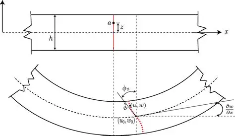
- Plane section before deformation remains plane after deformation
- cross-section of the beam is perpendicular to the neutral axis before deformation and after deformation, with no transverse shear deformation.
This theory effectively assumes a beam is infinitely stiff against shear, and deflection are only caused by bending moment.
Timoshenko Theory
When beams bend, they do not just curve gracefully due to bending moments; their cross-sections also experience shear deformation which is internal sliding distortions where parallel planes slip past one another. However, this distortion is very negligible in thin beams which makes Euler’s simplification acceptable. As for deep and short beams, the distortion becomes pronounced and cannot be ignored. The Timoshenko theory extends the classical model by accounting for this shear deformation and rotational inertia, making it more accurate for short, deep, or composite beams.
The cornerstones of Timoshenko beam theory are:
- Plane section before deformation remains plane after deformation (just like as assumed in Euler’s theory!)
- cross-section perpendicular to the neutral axis before deformation can rotate about the neutral axis to account for shear deformations
Application of Timoshenko Theory in Linear-Static Analysis of Beam Element
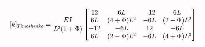
Shear deformation can be accounted for during analysis of a beam when required by using a shear deformation parameter ɸ, which represents the shear-to-bending flexibility ratio for the beam element
$\phi=\frac{12 E I}{G A_S L^2}$
where:
E is elastic modulus of the material
I is second moment of area of the beam’s cross‑section.
G is shear modulus of the material.
As is effective shear area (often corrected by the shear factor k. For a rectangular cross‑section, k= 56, for circular sections, k≈910. Other shapes have different values derived analytically or numerically.)
L is length of the beam
Deflection of Simply Supported Beams
For Euler bending theory, deflection is governed by purely bending deformations and for a simply-supported beam subjected to a uniformly distributed load, deflection at any point is:
$\mathrm{v}(\mathrm{x})=\frac{q L^4}{384 E I}\left(x^2-\frac{x^3}{L}\right)$
where;
v(x): is the vertical displacement
L : is the span of the beam
E: is the elastic modulus of the material
I: is the second moment of area
x: is the position along the length of the beam
However, for Timoshenko beam theory, deflection is governed by both bending and shear deformations and for a simply-supported beam subjected to a uniformly distributed load, deflection at any point is:
$\begin{aligned} & \mathrm{v}(\mathrm{x})=v_{\text {bending }}(\mathrm{x})+v_{\text {s.deformation }}(\mathrm{x}) \\ & \mathrm{v}(\mathrm{x})=\frac{q L^4}{384 E I}\left(x^2-\frac{x^3}{L}\right)+\frac{q L^4}{8 G A k}\left(1-\frac{x}{L}\right)\end{aligned}$
All parameters in the equation are as stated earlier in this article.
Deflection of Indeterminate Beams
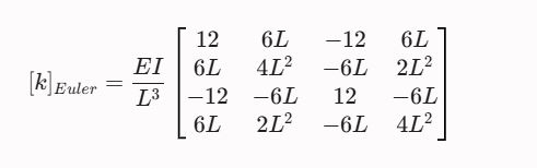
Indeterminate beams can be analyzed using several methods, however the FEM-based and computational-inclined technique which is the direct stiffness method will be considered. In this framework, the stiffness matrix of each beam element governs how loads translate into deformations. To capture the effects of shear deformation, the stiffness matrix can be modified. This is shown below where the stiffness matrix of a beam element using Euler’s beam model is re-rendered as Timoshenko’s beam model to account for shear effects where it cannot be neglected.
Stiffness Matrix Using Euler’s Beam Model
The Stiffness matrix using Timoshenko’s beam model